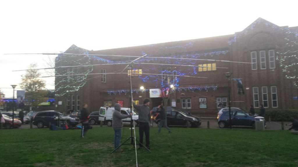
About five years ago, the club was generously donated a disused HF Yagi; specifically a Cushcraft A-3S tri-band beam designed for the 10, 15, and 20 metre Amateur Radio bands. This used to reside on a Scout Hut near Basingstoke, but sadly the licensed amateurs moved away and therefore the mast had to be decommissioned. Since then, the Yagi had been sat in various different locations in a state of disrepair.
It has been a long-standing goal of the club to establish a working shack, and to this end the Students’ Union gave us some funding so we could build a new multi-antenna mast. The HF Yagi was going to be the centrepiece of this mast. However, due to the complexities of deploying such infrastructure on the University campus, this has not yet happened. Nevertheless, as part of the funding was intended to refurbish existing equipment, bringing the Yagi up to spec was really the only thing we could currently do with the funding. We may not be able to raise the Yagi up to a height where it would be most effective but at least we can use our telescopic mast for temporary, less elevated, erections.
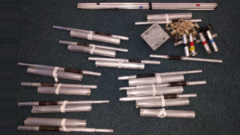
In order to achieve this, we first needed to make an initial assessment of what parts were present and which parts were missing or broken, logging all this information on wiki page. Once we had a rough idea of what we needed we could start looking into how much that might cost to order from Cushcraft. At the same time, we decided the that the present components needed a good clean up. After using an inordinate amount of wire wool, everything looked rather shiny and new.
Next, we disassembled the traps, which was a lot more difficult than we had hoped, but the good news was that they looked to be in a fairly good condition. Even so, it was clear that some of the black plastic end caps and internal white plastic spacers would need replacing. We decided that it would be a good idea to replace all the screws that attached the coils to the rest of the trap, as in most cases these were quite rusty.
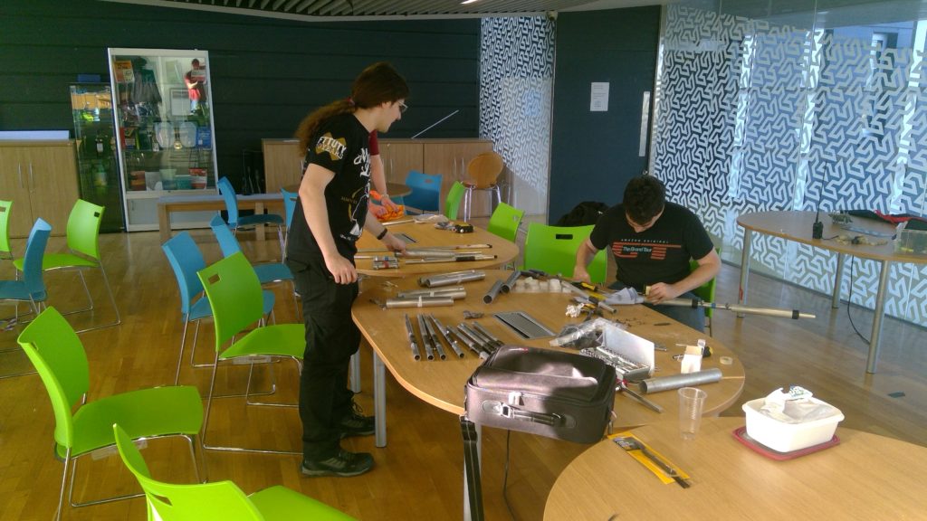
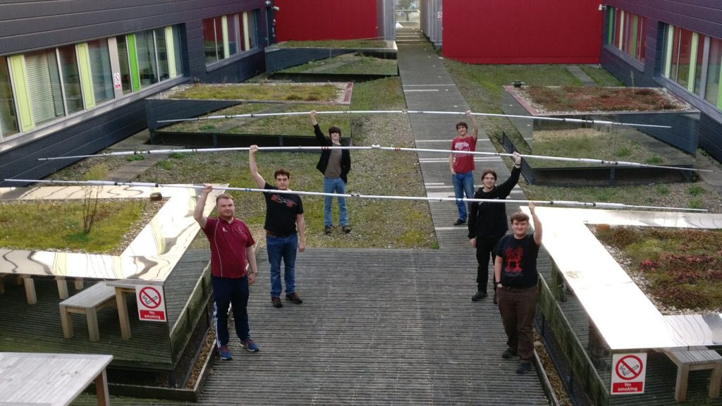
In early November 2017, we finalised and sent off our order to Cushcraft. Despite them being in the US the order was delivered quite promptly, so we scheduled a workshop for 19th November to assemble the Yagi for the first time. Despite hitting a number of issues during the course of the day, we managed to fully assemble the driver, reflector and director elements, just before it got dark.
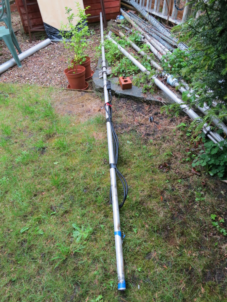
The following Sunday afternoon we decided that we decided to try to test the HF Yagi. Although we had the original boom, which came in two parts joined by an overlapping connecting aluminium tube, it was still too large for the storage we had available. Finding a solution to this problem was less than straightforward, as it looked like the connecting tube was the same diameter as the two parts of the boom but had been cross cut so it could stretch around them. Eventually, we decided to saw through the overlapping connector where we thought the two boom parts meet. We needed to come up with a new solution for the boom.
We acquired a 15ft aluminium tube, which we hoped to use as a solid boom but it turned out the diameter was too great the U-bolts for attaching the elements would not fit round. We had a couple of sections of an interconnecting mast but this only came to 10ft. Therefore we needed to reuse half of the old boom to make this ad-hoc boom sufficiently long. After, securing the interconnecting parts of the boom using jubilee clips — and a bit more tinkering to fit the U-bolts round the boom — we eventually got the HF Yagi erected just before it got dark.
Although we could not get the HF Yagi as high as we would have liked, as our telescopic guyed mast would only allow us to raise it 3 metres above the ground, this was sufficient for basic testing of the mast. Using our new portable operating table, our FT-920, and new tuner donated by an alumni, we tested the Yagi on all three bands (10, 15 and 20 metres). The SWR was good on the 15m band, but the 10m and 20m bands required the use of a tuner in order to improve the SWR. This behaviour was unexpected, and implies that the RF traps could be faulty. A VNA is required to do a frequency sweep and identify what is causing the fault.

