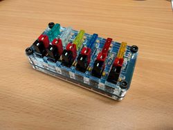
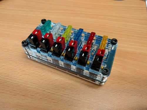
Powerpole Distribution
From SUWS-wiki
| Powerpole Distribution Box Project | |
|---|---|

| |
| Status | Completed |
| Project Lead | User:TylerWard |
Powerpole Distribution Box Project
A DC power distribution board using Anderson powerpole connectors
Status
- Completed, designs are available at Github
Feature List
- 6 power-pole connectors
- Individually fused connections with indicators
- 30A capacity (Limited by current rating of the fuse holders)
Costings
Costings below are for individual orders the main club order will be cheaper
| Type | Item | Cost | Link |
|---|---|---|---|
| connector | 12*45A pcb contacts | £9.90 for 15 | [1] |
| connector | 6* red 45A housings | £2.65 for 10 | [2] |
| connector | 6* black 45A housings | £2.65 for 10 | [3] |
| Fuseholder | Keystone 3522 | £6.56 for 100 | [4] |
| Resistor | 330ohm though hole 0.25w | £0.23 for 10 | [5] |
| LED | 3mm red/yellow | £0.24 for each | [6] |
| PCB | 5*10cm 2oz blue | $40.95 for ~10 or (£3 each) | [7] |
Build instructions
Tools Required
- Soldering iron - high power (45W+) with a large tip as there is a large thermal mass.
- Sidecutters
- (Recommended) Helping hands or other PCB support tool.
Instructions
- Solder resistors, capacitors and LEDs onto the PCB.
- Push fuse holder contacts through the holes in the PCB.
- Solder fuse holder contacts. These will suck up the heat, so may take a while to get up to temperature.
- Attach the to top two acrylic layers and attach the partly-populated PCB using the nuts and bolts provided.
- Assemble the powerpole contacts by joining them together and inserting the contacts into their housings.
- Place the powerpole contacts onto the PCB. To ensure correct placement, the top acrylic layers should be fitted first, otherwise the spring of the powerpoles will cause these layers to be offset.
- Solder the powerpole contacts onto the PCB. The most straightforward way found to do this is to push the PCB and powerpole contacts down onto a hard heatproof surface, so that they sit in the correct place whilst they are soldered. They should be soldered as quickly as possible to avoid the powerpole housings melting due to too much residual heat.
- Check for any solder bridges across both the fuses and powerpoles.
- Assemble the remaining two acrylic layers of the case and attach to the already assembles layers and PCB.
- Enjoy your Distro!

